Injection Molds
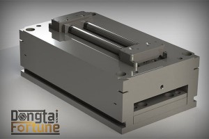
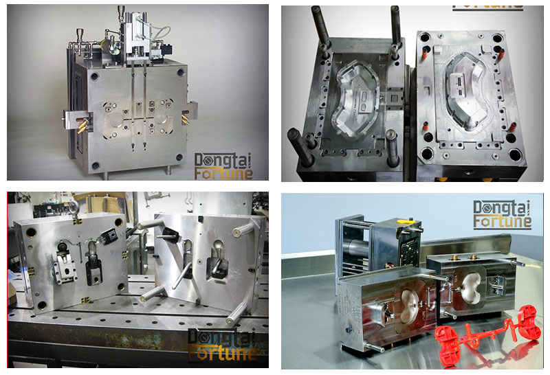
The injection molding process uses molds, typically made of steel or aluminum, as the custom tooling. The mold has many components, but can be split into two halves. Each half is attached inside the injection molding machine and the rear half is allowed to slide so that the mold can be opened and closed along the mold’s parting line. The two main components of the mold are the mold core and the mold cavity. When the mold is closed, the space between the mold core and the mold cavity forms the part cavity, that will be filled with molten plastic to create the desired part. Multiple-cavity molds are sometimes used, in which the two mold halves form several identical part cavities.
Mold base
The mold core and mold cavity are each mounted to the mold base, which is then fixed to the platens inside the injection molding machine. The front half of the mold base includes a support plate, to which the mold cavity is attached, the sprue bushing, into which the material will flow from the nozzle, and a locating ring, in order to align the mold base with the nozzle. The rear half of the mold base includes the ejection system, to which the mold core is attached, and a support plate. When the clamping unit separates the mold halves, the ejector bar actuates the ejection system. The ejector bar pushes the ejector plate forward inside the ejector box, which in turn pushes the ejector pins into the molded part. The ejector pins push the solidified part out of the open mold cavity.
Mold channels
In order for the molten plastic to flow into the mold cavities, several channels are integrated into the mold design. First, the molten plastic enters the mold through the sprue. Additional channels, called runners, carry the molten plastic from the sprue to all of the cavities that must be filled. At the end of each runner, the molten plastic enters the cavity through a gate which directs the flow. The molten plastic that solidifies inside these runners is attached to the part and must be separated after the part has been ejected from the mold. However, sometimes hot runner systems are used which independently heat the channels, allowing the contained material to be melted and detached from the part. Another type of channel that is built into the mold is cooling channels. These channels allow water to flow through the mold walls, adjacent to the cavity, and cool the molten plastic.
Mold design
In addition to runners and gates, there are many other design issues that must be considered in the design of the molds. Firstly, the mold must allow the molten plastic to flow easily into all of the cavities. Equally important is the removal of the solidified part from the mold, so a draft angle must be applied to the mold walls. The design of the mold must also accommodate any complex features on the part, such as undercuts or threads, which will require additional mold pieces. Most of these devices slide into the part cavity through the side of the mold, and are therefore known as slides, or side-actions. The most common type of side-action is a side-core which enables an external undercut to be molded. Other devices enter through the end of the mold along the parting direction, such as internal core lifters, which can form an internal undercut. To mold threads into the part, an unscrewing device is needed, which can rotate out of the mold after the threads have been formed.


